Maintenance
- 01 Mar 2025
- 39 Minutes to read
- Contributors

- Print
- DarkLight
- PDF
Maintenance
- Updated on 01 Mar 2025
- 39 Minutes to read
- Contributors
- Print
- DarkLight
- PDF
Article summary
Did you find this summary helpful?
Thank you for your feedback!
General & Preventive Maintenance

1. Maintenance Cautionary Notes
1.1 Important Precautions.
READ this manual before operating or servicing this equipment.
- ALWAYS remove power and wait at least 30 seconds before connecting / disconnecting any internal harnesses. Failure to observe these precautions may result in damage to, or destruction of the equipment.
- ALWAYS take proper precautions when handling static sensitive devices.
- SAVE this manual for future reference.
- DO NOT allow untrained personnel to operate, clean, inspect, maintain, service or tamper with this equipment.
- DO NOT connect or disconnect any digital or analogue components to the equipment with power connected or damage may result.
- Do not use any chemicals to clean this equipment, unless otherwise stated in this manual.
- When using compressed air to blow down this equipment, do not direct the air stream at electric/pneumatic or other sensitive devices. Ensure correct PPE is used appropriately.
- Do not wet wash any of the equipment unless stated to do so.
- Report all defects immediately to your supervisor or manager.
- When first installed all surfaces must be cleaned of all foreign material.
Ensure all energy sources are isolated before attempting to clean this machinery. All loose product should be gently brushed off the machine components with a small hand brush. If a vacuum system is installed for cleaning purposes use a small application head to remove loose product from this equipment.
Where applicable, follow the manufactures instructions stated in the original equipment manual. All safety warnings and cautionary advice must be observed.
Cleaning should occur at the end of each day’s production or before maintenance work. Cleaning of every station and work area on the process and line equipment is very important.
Clean with a dry lint free cloth or soft brush; use a vacuum attachment if installed.
Include cleaning for these areas:
- All access points including guards.
- All the floor area underneath and around the machine.
- Sensors and switches.
- Motors and gearbox units.
- Pneumatic cylinders and fittings.
- Internal and external surfaces and the dust extraction ducting including flexible tubing.
- All product contact surfaces must be cleaned to an acceptable hygiene level.
If the product has been exposed to moisture and solidified a scraper with a hard plastic blade can be used. Under no circumstances is a metal blade scraper to be used. Once the hardened product has been removed the scraper and the cleaned area must be wiped down. Any wet areas after washing must be cleaned using a clean dry cloth. Wipe all areas afterwards using a clean dry cloth.
1.2 Personnel.
- Only qualified personnel are permitted to operate, adjust, service or maintain `B
- Personnel are prohibited from interfering with machinery in any way when it is in operation.
1.3 Safety.
.png) WARNING
WARNING
Safety screens and covers must be maintained where fitted and replaced in the correct position after maintenance or servicing is completed.
1.4 Service, Repair & Adjustments.jfif)
- Before servicing or repairing, stop the machine and disconnect all energy sources.
- Maintenance and adjustments must be performed with all energy sources isolated unless otherwise specified in this manual.
- To isolate the machinery, refer to the “warning” page in this manual.
1.5. Pneumatic Supply
- High pressure pneumatic systems are dangerous.
- Do not service or troubleshoot systems with the compressed air supply on. Be sure to bleed off any trapped compressed air before working on components since it is possible to have high pressures trapped in the pneumatic or gas lines.
2. Maintenance Specifications
2.1 Recommended Lubricants.
Use these lubricants for the following items
| Item. | Lubricant. |
.jfif) SEW Gear motor. SEW Gear motor. | Mobil Mobil gear 630 (All “SA” series worm geared gearboxes use Mobil 636). |
.jfif) Bearing. Bearing. | Mobilux EP2. |
.jfif) Linear bearing. Linear bearing. | Mobilux EP2. |
.jfif) Chain Chain | Rocol Food Grade Chain Lube - AQIS approved. |
.jfif) Pneumatic cylinder. Pneumatic cylinder. | Silicon grease. |
2.2 Pneumatic Cylinder Torques.
For further information please refer to the OEM or the manufacturer.
2.3 Pneumatic System Settings.
Pneumatic Pressure – Regulator.
Machine circuit. | Regulator pressure. | |
| kPa | psi |
Pneumatic service unit. | 600 | 87 |
3. Maintenance Schedule
3.1 Main Drive Maintenance Schedule
3.1.1 Bearings, Bushes and
Task ID. | Daily. | Weekly. | Monthly. | 3 Monthly. | 6 Monthly. |
Grease linear bearings. |
| X |
|
|
|
Inspect bushes. |
| X |
|
|
|
Inspect cam tracks |
| X |
|
|
|
Inspect and Grease bearings, as applicable. |
|
|
| X |
|
Inspect linear bearing tracks. |
|
|
| X |
|
Inspect linear bearing bolts. |
|
|
| X |
|
Grease spherical ball ends where applicable. |
|
|
| X |
|
3.1.2. Motors, Gearboxes, & Brakes.
Task ID. | Daily. | Weekly. | Monthly. | 3 Monthly. | 6 Monthly. |
Grease electric motors if required. |
|
|
|
| X |
Inspect motor brake adjustments. |
|
|
|
| X |
Inspect oil level. |
|
|
|
| X |
3.1.3. Belts and Pulleys/Chains and Sprockets.
Task ID. | Daily. | Weekly. | Monthly. | 3 Monthly. | 6 Monthly. |
Inspect for product build up | X |
|
|
|
|
Inspect chain and sprockets. |
|
| X |
|
|
Inspect belts and pulleys. |
|
| X |
|
|
Inspect belt/chain tension |
|
| X |
|
|
Inspect belt/chain alignment. |
|
|
|
| X |
3.2. Enclosure Maintenace Schedule.
Task ID. | Daily. | Weekly. | Monthly. | 3 Monthly. | 6 Monthly. |
Clean photo eyes, reflectors and proximity sensors | X | ||||
Inspect the fan filter in control console (if fitted). | X | ||||
Inspect proximity switch adjustments. | X | ||||
Inspect reed switches. | X | ||||
Inspect mechanical switches. | X | ||||
Inspect the | X | ||||
Inspect wiring (visual). | X | ||||
Inspect all other switches and buttons. | X | ||||
Test 24-volt DC supplies for adjustment. | X | ||||
| All cabinet wiring shall be inspected prior to power up | X | ||||
| Random ferrule tagging visual check, should be clear and readable | X | ||||
| Random Point to Point (resistance test) | X | ||||
| Random Point to Ground (resistance test) | X | ||||
| Earth bonding test shall not execute 0.1 ohms between bounded item and earth bus bar, use megger to check earthing | X | ||||
| Randomly check the wiring for proper crimping & termination (Tug test) | X | ||||
| Check the cabinet are connected to a suitable earthing point in the FAT premise | X | ||||
| Check all MCB's for the correct rating protection (refer to Electrical Drawing) | X | ||||
| Switch ON circuit breaker 'MCB', check voltage on its output terminals. | X | ||||
| Ensure no alarm on the IO modules after power up of the 24V DC field power supply | X | ||||
| For each type of power feed, measure voltage & total system current with system "No-Load" condition and record the results | X |
3.3. Flap Folding Maintenance Schedule.
Task ID. | Daily. | Weekly. | Monthly. | 3 Monthly. | 6 Monthly. |
Inspect vacuum filters | X |
|
|
|
|
Clean vacuum cups | X |
|
|
|
|
Inspect all pneumatic cylinder mounts. |
| X |
|
|
|
Clean vacuum filters |
| X |
|
|
|
Inspect the pneumatic service unit. |
|
| X |
|
|
Inspect valves |
|
| X |
|
|
Test pressure and inspect sensor switch settings. |
|
|
| X |
|
Inspect all regulators and settings. |
|
|
|
| X |
Test all pneumatic cylinders for air leaks. |
|
|
|
| X |
Inspect the pneumatic system (all lines and fittings). |
|
|
|
| X |
3.4. Chassis Maintenance Schedule.
Task ID. | Daily. | Weekly. | Monthly. | 3 Monthly. | 6 Monthly. |
Inspect for product build up. | X |
|
|
|
|
Inspect all nuts and bolts. |
|
|
|
| X |
Inspect for stress fatigue fractures. |
|
|
|
| X |
| Check all Doors for proper Operation | X | ||||
| Check all lights for proper operation (refer Scada screens manual) | X |
3.5 Infeed & Outfeed Conveyor Maintenace Schedule
3.5.1 Bearings, Bushes and
Task ID. | Daily. | Weekly. | Monthly. | 3 Monthly. | 6 Monthly. |
Grease linear bearings. |
| X |
|
|
|
Inspect bushes. |
| X |
|
|
|
Inspect cam tracks |
| X |
|
|
|
Inspect and Grease bearings, as applicable. |
|
|
| X |
|
Inspect linear bearing tracks. |
|
|
| X |
|
Inspect linear bearing bolts. |
|
|
| X |
|
Grease spherical ball ends where applicable. |
|
|
| X |
|
3.5.2. Motors, Gearboxes, & Brakes.
Task ID. | Daily. | Weekly. | Monthly. | 3 Monthly. | 6 Monthly. |
Grease electric motors if required. |
|
|
|
| X |
Inspect motor brake adjustments. |
|
|
|
| X |
Inspect oil level. |
|
|
|
| X |
3.5.3. Belts and Pulleys/Chains and Sprockets.
Task ID. | Daily. | Weekly. | Monthly. | 3 Monthly. | 6 Monthly. |
Inspect for product build up | X |
|
|
|
|
Inspect chain and sprockets. |
|
| X |
|
|
Inspect belts and pulleys. |
|
| X |
|
|
Inspect belt/chain tension |
|
| X |
|
|
Inspect belt/chain alignment. |
|
|
|
| X |
3.6 Booklet Pick & Place Maintenance Schedule
3.6.1 Bearings, Bushes and
Task ID. | Daily. | Weekly. | Monthly. | 3 Monthly. | 6 Monthly. |
Grease linear bearings. |
| X |
|
|
|
Inspect bushes. |
| X |
|
|
|
Inspect cam tracks |
| X |
|
|
|
Inspect and Grease bearings, as applicable. |
|
|
| X |
|
Inspect linear bearing tracks. |
|
|
| X |
|
Inspect linear bearing bolts. |
|
|
| X |
|
Grease spherical ball ends where applicable. |
|
|
| X |
|
3.6.2. Motors, Gearboxes, & Brakes.
Task ID. | Daily. | Weekly. | Monthly. | 3 Monthly. | 6 Monthly. |
Grease electric motors if required. |
|
|
|
| X |
Inspect motor brake adjustments. |
|
|
|
| X |
Inspect oil level. |
|
|
|
| X |
3.7. Pick Head Maintenance Schedule.
Task ID. | Daily. | Weekly. | Monthly. | 3 Monthly. | 6 Monthly. |
Inspect vacuum filters | X |
|
|
|
|
Clean vacuum cups | X |
|
|
|
|
Clean vacuum filters |
| X |
|
|
|
Inspect the pneumatic service unit. |
|
| X |
|
|
Inspect valves |
|
| X |
|
|
Test pressure and inspect sensor switch settings. |
|
|
| X |
|
Inspect all regulators and settings. |
|
|
|
| X |
Test all pneumatic cylinders for air leaks. |
|
|
|
| X |
Inspect the pneumatic system (all lines and fittings). |
|
|
|
| X |
| Inspect & tight the Grub Screw of the Pick Head | X |
3.8 Camera System Maintenance Schedule
| Task ID | Daily | Weekly | Monthly | 3 Monthly | 6 Monthly |
| Clean lens before every assignment or whenever needed | X | ||||
| Clean lens by putting cleaning fluid on lens tissue and use a circular motion to wipe the lens from the center to the outer edge | X | ||||
| Maintain tripod and camera body before and after every use. | X |
4. Lubrication System
lubrication system is a critical component of any machinery that relies on the movement of mechanical parts. The purpose of a lubrication system is to provide lubrication or oil to the various moving parts of a gears or machinery to reduce friction and wear and tear, prevent overheating, and increase the lifespan of the machinery.
Please refer the below Lubrication Schedule
4.1 Chains(1).jfif)
Procedure. | Follow this procedure to lubricate a Chain. Excludes self-lubricated chains. |
Step. | Action. |
Remove excessive foreign material from around the drive chain and sprockets. Use a lint free clean dry cloth or a soft brush. | |
2. | Inspect the condition of the chain and sprockets. |
3. | Service the chain with a recommended lubricant. Refer to recommended lubricants in Maintenance Specification. |
4.2 Bearings.
(1).jfif)
Procedure. | Follow this procedure to inspect a Sealed for Life Bearing. |
Step. | Action. |
1. | Remove excessive foreign material from around the bearing. Use a lint free clean dry cloth or a soft brush. |
2.. | Inspect the condition of the bearing. |
3. | This type of bearing does not require lubrication. |
Procedure. | Follow this procedure to lubricate a bearing with a Grease Nipple. |
Step. | Action. |
1. | Remove excessive foreign material from around the bearing. Use a lint free clean dry cloth or a soft brush. |
2. | Inspect the condition of the bearing. |
3. | Grease each bearing nipple with one shot of grease. Refer to recommended lubricants in Maintenance Specification. |
Procedure. | Follow this procedure to lubricate a Linear Bearing. |
Step. | Action. |
1. | Remove excessive foreign material from around the bearing. Use a lint free clean dry cloth or a soft brush. |
2. | Inspect the condition of the bearing. |
3. | Inspect the condition of the bearing runner and guide. |
4. | Grease each bearing nipple with one shot of grease. Refer to recommended lubricants in Maintenance Specification. |
Bearings (Continued).
Procedure. | Follow this procedure to lubricate a Spherical Rod End. |
Step. | Action. |
1. | Remove excessive foreign material from around the bearing. Use a lint free clean dry cloth or a soft brush. |
2. | Inspect the condition of the bearing. |
3. | Grease each bearing nipple with one shot of grease. Refer to recommended lubricants in Maintenance Specification. |
4.3 Gear Motor / Gearbox
(1).jfif)
Procedure. | Follow this procedure to lubricate a Gear Motor / Gearbox. |
Step. | Action. |
1. | Remove excessive foreign material from around the unit. Use a dry clean lint free cloth. |
2. | Remove the oil level plug. |
3. | Inspect the oil level is at the bottom edge of the threaded hole. |
4. | Use a dip stick to remove a sample of oil and inspect the condition. Replace with recommended oil if required. Refer to recommended lubricants in Maintenance Specification. |
5. | If the oil level is low, add oil slowly through one of the upper plugholes. |
6. | Replace all plugs; clean any oil spills with a clean lint free cloth. |
7. | Test for leaks. |
5. Maintenance Procedures
5 .1. Bushes and Cam tracks.
Procedure. | Follow this procedure to maintain Bushes and Cam Tracks. |
Step. | Action. |
1. | Remove excessive foreign material. Use a dry lint free cloth. |
2. | Inspect bushes and cam tracks for excessive play and/or damage. Report excessive play or damage to your supervisor. |
Procedure. | Follow this procedure to maintain a Pneumatic Service Unit. |
Step. | Action. |
1. | Inspect the operational condition of the equipment. Test the isolation and lockout control is functioning correctly. Report any damage or safety issues to your supervisor and replace the unit. |
2. | Inspect the filter bowl is clean. Clean with a dry lint free cloth if necessary. |
3. | Inspect the pneumatic filter for debris. Clean or replace if necessary. |
4. | Test for pressure on the pneumatic regulator gauge. Adjust if necessary and ensure handle is returned to the locked position to prevent self adjustment resulting from vibration. Refer to Maintenance Specification for pneumatic pressure setting. |
5. | Ensure seals are in good condition. |
6. | Inspect all fittings and pneumatic lines, tighten if required. |
7. | Test for leaks. |
8. | Clean the pneumatic service unit and any spills. |
5 .3 Belts and Pulleys/Chains and Sprockets. .jfif)
Procedure. | Follow this procedure to inspect the Belts and Pulleys/Chain and Sprockets. |
Step. | Action. |
1. | Inspect for any physical wear and tear. Report any defects to your supervisor. |
2. | Test belt tension is sufficient to avoid slippage. |
3. | Inspect pulleys are not slipping on the shaft and are aligned with the transmission belt and correctly tensioned. |
5.4 Drive Belt Tension.
Procedure. | Follow this procedure to tension Drive Belts. |
Step. | Action. |
1. | Check the alignment of all drive pulleys. |
2. | Adjust belt tension by adjusting the four adjusting screws on motor mount plate. Drive belt tension should be approximately 5 mm deflection over a 300 mm span (measured at centre of span). Refer Fig 1. |
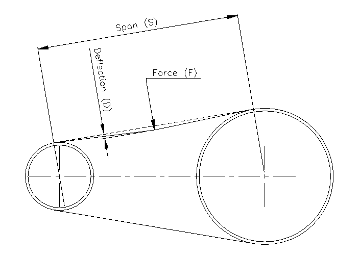
Fig 1
5.5 Chain Tension.
Procedure. | Follow this procedure to tension drive chains. |
Do not over-tension a chain. Excessive tension can lead to premature drive component failure and possible misalignment.
Step. | Action. |
1. | Check the alignment of all drive sprockets. |
2. | Adjust chain sag to match the table below. |

5 .6 Pneumatic Cylinders.
Procedure. | Follow this procedure to inspect a Pneumatic Cylinder. |
Step. | Action. |
Inspect the nose cone seal for leaks; this is typically the first area of leakage. | |
Visually inspect that the cylinder operates smoothly. Inconsistent operation indicates that the cylinder requires servicing or needs to be replaced by suitably qualified personnel. | |
Inspect the wiring to ensure the cable is not damaged. |
5 .7 Pneumatic Cylinder Mounts.
5.8 Reed Switches
Procedure. | Follow this procedure to maintain a Reed Switch. |
Step. | Action. |
1. | Clean the body with a soft dry lint free cloth or soft brush. Note any setting and position. |
2. | Test if the sensor is functioning correctly. Is the LED indication visible when the cylinder is extended or retracted? If the LED is not visible check if the reed switch is securely attached to the cylinder. |
3. | Inspect the cylinder to determine if it is functioning correctly. If necessary, adjust the position of the reed switch until the correct setting is found. Repositioning the reed switch must be within the operating parameters of the cylinder. |
4. | Inspect the wiring to ensure the cable is not damaged. |
5. | If the sensor is not responding to adjustments report the defect to your supervisor. All reed switches must be replaced by suitably qualified personnel. |
5 .9 Chassis and Fasteners. .jfif)
Procedure. | Follow this procedure to maintain a Fasteners |
Step. | Action. |
1. | Clean with soft dry lint free cloth. |
2. | Visually inspect for fatigue or stress fracture. Inform manager if found. |
3. | Inspect for loose fasteners. Lock tight/replace as appropriate any lose or worn fasteners. |
5 .10 Photo Electric Sensors.
.jfif)
Note: Click on the Image for the Manual
Procedure. | Follow this procedure to maintain a Photo Electric Sensor. | |
Step. | Action. | |
1. | Clean the lens and body with a soft dry lint free cloth or soft brush. Note any setting and position. | |
2. | Test if the sensor is functioning correctly. Is the LED indication visible when covered or uncovered? Adjust the sensitivity of the sensor if necessary and check again until the correct setting is found. If the sensor is not responding to adjustments report the defect to your supervisor. All photoelectric sensors must only be replaced by qualified personnel. | |
Procedure. | Follow this procedure to secure and adjust the sensitivity of a Photo Electric Sensor. | ||
| Step. | Action. | |
| 1. | Adjust the sensitivity to the maximum setting by turning the sensitivity potentiometer, this is normally indicated by a ‘+’ symbol. The adjustment can usually be made either on the back or top of the unit. | |
| 2. | Aim the receiver unit at the sender unit until the LED indicator on the receiver unit turns [on] (light switching) or [off] (dark switching if the LED is permanently on). | |
| 3. | To be certain the sensor beam is centred, sweep the sender unit across the receiver unit in the vertical plane and determine the position where the LED indicator turns [on] and then [off]. It is important to ensure that the sensor units are also aligned in the horizontal position. When in the correct position the fixings on the brackets can be tightened. Do not over tighten the fixing screws on the sensor as this will damage or impair the function of the unit. | |
| 4. | Reduce the sensitivity by turning the potentiometer towards the ‘–‘ symbol until the LED indicator begins to flicker or goes out completely. Slowly turn the potentiometer back in small increments in the ‘+’ direction until the LED indicator displays a solid indication. | |
| 5. | It may be necessary to reduce the sensitivity to a lower setting for transparent or translucent materials or to detect objects smaller than the effective beam. | |
| 6. | Test operation and adjust if necessary. | |
5 .11 Proximity Switches.
(1).jfif)
Note: Click on the Image for the Manual
Procedure. | Follow this procedure to maintain a Proximity Switch. | |
Step. | Action. | |
1. | Clean the threaded barrel proximity switch with a dry clean lint free cloth or soft brush. Check the condition of the proximity switch and cable. If damaged report the defect to your supervisor. | |
2. | Test the operation of the proximity switch by observing if the LED indicator alternates between on and off when using a test piece to activate it. | |
3. | Read the information on the proximity switch. Contained in this is the part code and sensing range. Ensure you test within the sensing range of the proximity switch. | |
4. | To adjust the air gap, gently slacken off the locknuts of the proximity switch. | |
5. | Set the air gap to suite the sensing range of the proximity switch. Ensure the LED on the proximity switch is visible. | |
6. | Tighten the securing locknuts. | |
7. | Test the operation of the proximity switch and make further adjustments if necessary. | |
5 .12 Safety Interlock Switches
Note: Click on the Image for the Manual
Procedure. | Follow this procedure to maintain and replace a Safety Interlock Switch component. |
Step. | Action. |
1. | Clean the switch head and body with a soft dry lint free cloth or soft brush. Note all settings and positions. |
2. | Inspect the condition of the actuating head, switch body and the cable. If any damage is found report it to your supervisor. |
3. | If the actuator or head needs to be replaced, it is important to note all positions and connections before commencing any work. Slacken off all fixing screws, and remove the damaged component. The component must be replaced with a compatible part. It is important to use the correct tools and securely tighten terminals and the component after installation. |
4. | Secure the actuator or switch in its original position and test the operation. |
5. | Make adjustments and fully tighten all fixings when the set-up is complete. |
5 .13 Servo Motors
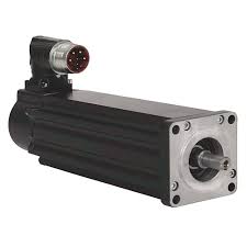
Note: Click on the Image for the Manual
Procedure. | Follow this procedure to maintain a Servo Motor component |
| Step. | Action |
| 1. | Maintain the room temperature between 20ºC and 25ºC. If, for example, the working temperature of the variable frequency drives (VFD) increases by 15ºC, its working life will be three times shorter. |
| 2. | Avoid dust. the accumulation of dust inside the equipment can cause the bad functioning of the motors and lead to downtime. |
| 3. | The humidity must be between 40% and 55%. This humidity range is high enough to prevent static electricity and low enough to prevent condensation. |
| 4. | Placing the equipment in racks or in air-conditioned rooms will help to make the equipment’s working life longer and minimalize its maintenance. This option is not always possible, but what we can do is keep the drives and controllers as clean as possible |
5 .14 Servo Drives
.jpg)
Note: Click on the Image for the Manual
Procedure. | Follow this procedure to maintain a Servo Drive component |
| Step. | Action |
| 1. | Maintain the room temperature between 20ºC and 25ºC. If, for example, the working temperature of the variable frequency drives (VFD) increases by 15ºC, its working life will be three times shorter. |
| 2. | Avoid dust. the accumulation of dust inside the equipment can cause the bad functioning of the motors and lead to downtime. |
| 3. | The humidity must be between 40% and 55%. This humidity range is high enough to prevent static electricity and low enough to prevent condensation. |
| 4. | Placing the equipment in racks or in air-conditioned rooms will help to make the equipment’s working life longer and minimalize its maintenance. This option is not always possible, but what we can do is keep the drives and controllers as clean as possible |
5.15 Pneumatic Energy System.
Procedure. | Follow this procedure to maintain a Pneumatic Energy system. |
Step. | Action. |
1. | Remove excessive foreign material from on or around tubing and equipment. Use a dry clean lint free cloth or soft brush. |
2. | Inspect the equipment and tubing for damage. Report any defects to your supervisor. |
3. | Tighten fittings; ensure the tubing is pushed securely into the fittings. |
4. | Ensure restrictor locking nuts are in place and finger tight. |
5. | Inspect all equipment and fixings are secure and tight. |
6. | Check that the equipment and tubing identification labels are present, replace if necessary. |
7. | Test the supply pressure and inspect sensing devices. |
8. | Test operation and make adjustments if necessary. (Refer to the Maintenance Specification section) |
5 .16 PLC Battery Check.
Procedure. | Follow this procedure to maintain the |
Step. | Action. |
1. | Check that the service date is written on the battery cover. |
2. | If the LED warning light indicating the battery has failed is on, replacement the battery immediately. Under no circumstances, turn the power off to the |
5.17 Fan Filter.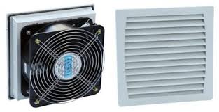
Procedure. | Follow this procedure to clean vacuum filters and for inspection of valves. |
Step. | Action. |
1. | Visually inspect valves for damage. Report any damage to your supervisor. |
2. | Visually check vacuum filter inspection window. Remove window to clean filter. |
3. | Remove filter elements from vacuum filter and clean/replace as required. |
5.19 Vacuum Cups.jfif)
Procedure. | Follow this procedure to clean vacuum cups. |
Step. | Action. |
1. | Visually inspect cups for damage to the cup lips. Inform your manager if the cups are damaged. |
2. | Blow out the holes in bottom of cups. |
3. | Clean the contact faces of the cup with an approved silicon spray on a clean lint free cloth. |
5.20 Pneumatic Service Units.
Procedure. | Follow this procedure to inspect pneumatic service units. |
Step. | Action. |
1. | Inspect pneumatic tubing for damage, leaks, or wear. |
2. | Inspect pneumatic regulator gauges operate correctly. Refer to “Maintenance Specification” in section 5.2 for the Pneumatic system Settings. |
3. | Inspect all fixings and connections are tight. |
4. | Inspect pneumatic filters. |
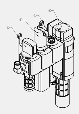
No. | Item. | Comments. |
1. | On / Off Valve | Turns air off to the machine |
2. | Filter/ Regulator | Filters small particles and regulates pressure |
3. | Branching Module | Used for air supply that won’t be dumped on e-stop |
4. | Monitored Safety Dump Valve | Dumps compressed to the machine |
For default pneumatic settings, please refer to “Maintenance Specification” in section 5.2.
6. Maintenance Drawing
- 16049-1703 Drive Assembly Maintenance
- 16049-1705 Belt Assembly Maintenance
- 16049-1706 Take up Assembly Maintenance
- 16049-1801 Flap Folding Assembly -Maintenance
- 16049-1804 Top Flap Slide Assembly Maintenance
- 16049-1815 Flap Folding Frame Assembly Maintenance
- 16049-2301 Infeed Conveyor Assembly Maintenance
- 16049-2701 Booklet pick and place Assembly Maintenance
- 16049-3101 Outfeed Conveyor Assembly Maintenance
Was this article helpful?