Operation of Machine
- 11 Mar 2023
- 20 Minutes to read
- Contributors

- Print
- DarkLight
- PDF
Operation of Machine
- Updated on 11 Mar 2023
- 20 Minutes to read
- Contributors
- Print
- DarkLight
- PDF
Article summary
Did you find this summary helpful?
Thank you for your feedback
Operation of Machine
1. Instructions
1.1 Operator Duties
The Operator will:
- Maintain an overview of the entire machine.
- Monitor machine performance and investigate any alarms that occur and resolve or call maintenance.
1.2 HMI Navigation
Every page on the HMI has the same Top Banner on it.

- Press to navigate to the Main Control Screen.
- Displays the current logged in User
- Displays an Active Alarms popup. Press to navigate to the Alarm Page
- Alarm Acknowledge Button. If an alarm has already been acknowledged, the alarm can be found in the Main Menu under Alarm History.
1.3 Control Buttons
Operational Control Buttons on RML Machines use symbols that comply with the IEC-60417 standard. The colours do not comply with any standard, however we have implemented industry standards as a guideline.
Reference and Symbol | IEC Title | RML Title | IEC Function | BRML Function |
IEC 60417-5008
| “OFF” (Power) | “Off” (Not Ready for Safety Reset) | To indicate disconnection from the mains, at least for mains switches or their positions, and all those cases where safety is involved. | To indicate the machine is De-Energized and that there is a safety device preventing the machine from being Powered ON |
IEC 60417-5009
| Standby | Reset | To identify the switch or switch position by means of which part of the equipment is switched on in order to bring it into the Standby condition. | To indicate the machine is powered on but requires a Reset to bring it to an Idle State. |
IEC 60417-5011
| “ON/OFF” (Push button) | “Off” (Ready for Safety Reset) | To indicate connection to the mains, at least for mains switches or their positions, and all those cases where safety is involved. "OFF" is a stable position, whilst the "ON" position only remains during the time the button is de-pressed. | To indicate the machine is De-Energized and that it is in a state where it can be powered ON |
IEC 60417-5104
| Start | Start | To identify the Start Button. | To identify the Start Button. |
IEC 60417-5110A
| Stop | Stop | To identify the control or the indicator to stop the active function. | To identify the Stop Button. Stop will terminate all Sequences immediately, bringing the machine to a Rapid Stop. |
IEC 60417-5111A
| Pause, interruption | Hold | To identify the control or the indicator which stops operation intermittently and keeps the equipment in Operating Mode. | To identify the Hold Button. Hold will transition the machine to a Held State, allowing all the sequences to complete their current function |
IEC 60417-5459
| Eject | Complete | To identify the Eject Button. | To Complete a production run or eject the remaining product from the machine at the end of a production run. |


1.4 Side Control Bar
The Side Control Bar provides access to common machine functions. I.e., Start, Stop and Off buttons may be accessed from any display.
Pressing the RML logo in the Top Banner opens and closes the Side Control Bar.
.PNG)
- Start Push Button - Press to issue a Start command to the machine. When in the Execute state, this button will change to the Hold icon.
- Stop Push Button - Press to terminate all Sequences immediately, bringing the machine to a rapid stop.
- Off (Not Ready for Safety Reset) Push Button - This is shown when the machine is in the Aborted state and the E-Stop is pressed. When the E-Stop is released, the icon becomes the Off – Ready for Safety Reset button. If the machine enters the Stopped state, the icon becomes the Reset button.
- Details Radio Button - If this is turned on Start, Hold and Reset push buttons will launch a Selection confirmation display. This will provide information as to why the action cannot be performed, or state that the action is ready to be triggered.
- Overview Button -Press to launch the MMIC Display.
- Safety Device Button -Press to launch the Safety Display.
- Sequence Button -Press to launch the Sequence Display.
- Menu Button -Press to launch the Menu Display.
- Tracking Button -Press to launch the Tracking Display.
- Home Button -Press to Home the Machine.
1.5 HMI Main Control Screen
.PNG)
- Machine State Model. Displays the current State of the Machine
- Machine Status Bar. Provides information on the current machine state
- Information on the Current Recipe. Press here to launch the Recipe Display
- Machine selections. There are several different machine selections in this area of the screen. These are used to enable and disable different machine functions.
- Home button is pressed to reset all Sequences and home all Servo Motors. You would use this button if you need to home one of the Servo Motors, or if you wanted to reset all of the Sequences back to Step 0.
- Machine Statistics. Press to launch the dedicated Statistics Display.
- Information on the Batch Reporting. Press here to launch the Batch Reporting Display.
- Double Click on the Robot High Power button for Robot’s Power up.
1.6 Machine State Control

PackML Machine State Model has been implemented for the overall control of this machine. There are three machine state types that define the current condition of the machine:
- Acting State – represents a processing activity, i.e., Aborting, Clearing, Stopping, Resetting Un-holding, Holding, Un-Suspend, Suspending and Completing.
- Wait State – identifies that a machine has achieved a defined set of conditions, i.e., Aborted, Stopped, Idle, Held, Suspended and Completed.
- Dual State – a Wait State that is causing the machine to appear as an Acting State. There is only one Dual State: Execute.
The image above shows the 17 Machine States and transition paths between states. The operator uses the control buttons on the main overview page to transition from state to state.
PackML Machine State Model States
- Aborting: An E-Stop has been pressed or a Door has been opened while in a running or Holding state. All power and air is being removed from the zone. The machine will be brought to a rapid, controlled safe stop.
- Aborted: All power and air has been removed from the zone. The machine maintains relevant information to the Abort condition. A Safety Reset command will force a transition to the Clearing state.
- Clearing: Machine is to clear faults that may have occurred when aborting and that are present in the Aborted state, before proceeding to a Stopped state.
- Stopping: Machine executes a controlled and safe stop.
- Stopped: Machine is powered and stationary.
- Resetting: Machine enters an energized state awaiting a Start command. Machine will be homed in this State if necessary.
- Idle: Machine Resetting is complete and ready to start-up.
- Starting: Machines performs steps required to enter the Execute sate.
- Execute: Machine is operating and producing product.
- Holding: Machine is being brought to a controlled stop when executing.
- Held: Machine is paused either by operator or a fault occurs in the Execute state.
- Un-Holding: Machine is being prepared to re-enter the Execute state.
- Suspending: Machine is being prepared to enter the Suspended state.
- Suspended: Machine enters this state due to a request from out/in-feed.
- Un-Suspending: Machine is being prepared to re-enter the Execute state.
- Completing: Machine has run product to completion. Used at the End of a Production run to drain any remaining product from all machines within this zone. I.e. processing of product at the Infeed will stop.
- Complete: Machine is waiting for a Stop command that will bring the machine into the Stopped state.
Restart after an Emergency Stop or Monitored Guard being opened
Check the machine to see if the reason for the E-Stop activation or Guard Door opening has been cleared.
- If an E-Stop was activated, release all E-Stop buttons (Twist to release)
- If a Guard Door was opened, close any Guard Doors that are open.
Once the E-Stop has been released and Guard Doors are closed, press the RESET button on the Side Control Bar or Main Control Display. This will reset the safety system and bring the machine into the Idle State.
1.7 Machine Restart from Held or Suspended State
From Machine Fault:
- Check machine fault
- Carry out necessary actions to resolve the fault
- Once the fault has been cleared, press the START button on the Side Control Bar or Main Control Display.
From Line Fault:
- Check line fault
- Carry out necessary actions to resolve the fault.
- Once the fault has been cleared, the machine should automatically restart.
Ensure the safety system is reset, Press the Start push button on the Side Control Bar to start the machine
2. Menu Layout and Screens
2.1 Main Menu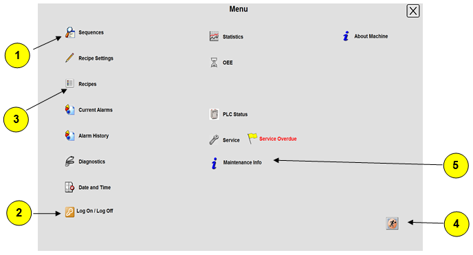

- Press to launch Sequence Screen
- Press to launch User Login Screen
- Press to launch the Recipe screen
- Press to shut down client file.
- Press to launch the manual & Electrical Drawing screen.
2.2 User Login

- Current User
- Touch to Login
- Touch to Logout.
Following is a matrix of the level access for each user, please note the Level 1-4 passwords are able to be altered for customer preference.
Level 5 are set aside for BRML Engineering access only to enable machine setup.

2.3 Mimic - Overview Display
The Overview Display provides an overview of the machine layout. Specific areas of the machine can be navigated to by using the Arrow buttons.
- Pressing this icon will launch the Mimic Overview Screen. This can be accessed from a display on the IPC
- These icons around the display will launch the Mimic indicated in the Arrow box when pressed. E.g., pressing the “Infeed” arrow box will launch a mimic for that area of the machine.
2.4 Mimic Overview – Device Legend
Photo-eye |
| Pushbutton |
| Light Stack | |
Direct Input |
| Direct Output |
|
| Fault |
E-Stop |
| Solenoid Valve |
| Alert | |
Proximity Sensor |
| Guard Door |
| Run | |
Switch/ Isolator |
| Safety Contactor |
| Servo |
|
Cylinder |
| Pneumatic |
| Motor |
|


.PNG)


Devices are shown in their approximate locations around the machine and have the following color indication.
- Green is On
- Grey is Off
- Red is Fault.
2.5 Mimic - Safety Screen
The Safety Mimic provides an overview of the machine. The safety devices are shown in their approximate locations around the machine and have the following color indication.
- Green is ready for Reset.
- Grey is Open.
- Red is in Fault.

- This area displays Safety Devices that are in the Main Control cabinet or are not in fields mounted on the machine.
- This is an indicator for a Door Switch.
- Green is Closed
- Grey is Open
- Red is in Fault.
Pressing this Icon will launch a face plate for this device.
- This is an indicator for an E-Stop.
- Green is Released
- Grey is Pressed
- Red is in Fault.
Pressing this Icon will launch a face plate for this device.
2.6 Mimic – Machine Module

- Device Indicator. These are.
- Green when on or running
- Grey when off
- Flashing red when in fault.
Pressing a device icon will launch a popup for that object.
- Tag Visibility toggle switch. When switched on, every device will have its tag name displayed beside it.
2.7 Sequences
Clicking on the Sequences button in the Menu launches this display.
Example: -

- Sequence Status. This displays the Sequence Name, Current Step and description of the current action that is taking place.
- Pressing this button launches another faceplate with more detail on that Sequence. That faceplate can be seen below.

2.8 Date and Time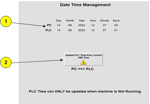

- Current PC Time. Hours, minutes and seconds can be updated by touching each field. If you wish to update the day, month or year you must first copy the time from the
- Pressing this button sets the PanelView Time to be the same as the
2.9 Batch Reporting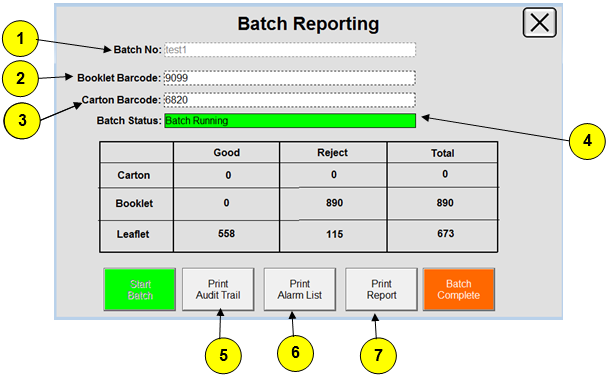

- Batch No.
- Click to Change the Booklet Barcode
- Click to Change the Carton Barcode
- Batch Status.
- Click to Print the Audit Trial
- Click to Print the Alarm List
- Click to Print the Report


2.10 OEE

- Use these tabs to click through OEE data for different shifts. The Green or Red Light Indicates weather the shift is active or not.
- Shift pattern setup. Use these fields to setup what time of the day each shift starts production and the length of each shift. Once set, the date will automatically update each day.
- OEE Break pauses the data collection and records the time that Break is active. This should be used for lunch breaks, smoko breaks, etc.
- OEE data for the currently selected shift. In the picture above it is Shift 1.
- Pressing this icon will launch the Machine Performance display for the current shift.
2.11 Setting up OEE Shift Patterns
- In the Start field, enter the Hour/Minute you wish to start the shift
- In the Shift Length field, enter the Hour/Minute to determine the shift length.
- Stop date and time will be auto generated.
2.12 Machine Performance

- Use these tabs scroll through machine performance data for different shifts.
- Machine Performance data for the currently selected shift. This measures the time spent in each state and the number of times the machine entered that state. In the picture above it is Shift 1.
3. Recipe
3.1 Recipe Settings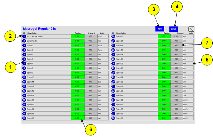

- Recipe Set points. These all have unique identifiers. These are all the parameters that are saved and loaded into and from the recipe files.
- Name of the Currently Loaded recipe
- Press here to alternate between the display containing all the Mechanical Recipe Setpoints and the display containing all the PLC System Recipe Set points.
- Use these buttons to navigate through the different pages of the project settings.
- The units the Set points are measured in.
- Current Setpoints.
- Recipe Setting is the Values saved in the recipe file. Red indicates that the current setting is different from the setting saved in the recipe file. Green indicates these two values are the same.
3.2 Recipe Mimic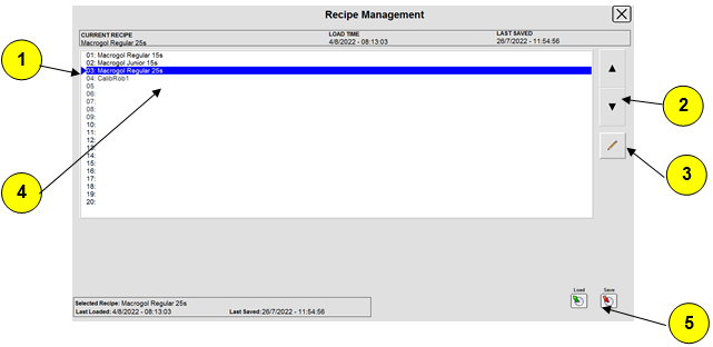

- The currently selected Recipe is highlighted in orange.
- Use these arrow keys to scroll through the different Recipe Files.
- Pressing this icon will open the Recipe Setting Page.
- Displays information for the recipe highlighted in the selection list
- Pressing these buttons, to Save or Load a recipe, will open a popup similar to the one below.

6. Press here to change the name of the file if you are performing a save.
7. Press OK to confirm that you want to save or load a file.
3.3 Loading a Recipe
- Using the arrow keys, Numeric Input or scanner, select the recipe you wish to load.
- Press the Load button
- A popup will show, asking for confirmation to load the selected recipe. Click OK.
3.4 Saving a Recipe
- Using the arrow keys, Numeric Input or scanner, select the recipe you wish to save.
- Press the Save button
- A popup will show, asking for confirmation to save the selected recipe. Click OK.
3.5 Creating new Recipe
- Using the arrow keys, Numeric Input or scanner, select a recipe file that is similar to the new product you wish to set-up.
- Load this File
- Scroll through the recipe list and find a blank location.
- Press Save.
- A Popup display will open. Enter the Name that you want to call the file into the text box and press OK
- This will save all the currently loaded setpoints into the new recipe file.
4. Face Plates
4.1 Mimic – Device Legend
Servo/Motor Status | Solenoid Valve Status | ||||||
| Running |
| On | ||||
| Stopped |
| Off | ||||
| Faulted |
| Faulted | ||||
Cylinder Status | |||||||
| Retract |
| Retract - Faulted | ||||
| Extend |
| Extend - Faulted | ||||
Selection Status | Miscellaneous Status | Device Status | |||||
| Running |
| Manual Active |
| On | ||
| Off |
| Service Due |
| Off | ||
| Queued |
| Safety Controller |
| Faulted | ||


.jpg)


4.2 Cylinder

- Tag name and description for the selected cylinder.
- Number of times the cylinder has been actuated.
- Cylinder status flags showing Output State, Reed Status, Alarm and Manual state.
- Timer pre-sets for the cylinder alarms. If the cylinder is setup as having no reed switches, these timers become extend and retract times for the cylinder.
4.3 Miscellaneous Input

- Tag name and description for the selected device.
- Current status of the device with de-bounce times applied
- Device Status
- De-bounce and Fault Times.
4.4 Miscellaneous Output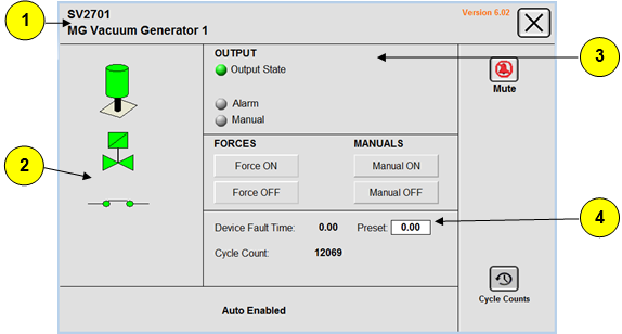

- Tag name and description for the selected device.
- Current State of the device.
- Current Status of the device.
- Fault timer and cycle counter.
4.5 Motors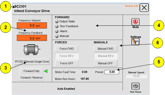

- Tag name and description for the selected motor.
- Frequency feedback and current target frequency.
- Current state of the motor.
- Status of the motor.
- Fault timer and run hours for the motor.
- Manual Controls. You must be logged in as a technician to gain access to these controls.
4.6 Servo Motor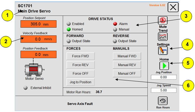

- Tag name and description for the selected servo.
- Velocity and Position feedback and current target position.
- Current drive status
- Pressing here will launch the servo settings display.
- Pressing here will launch a home selection screen. This will provide information about the homing of the axis.
- Manual Controls. You must be logged in as a technician to gain access to these controls.
4.7 Servo Setting This display is launched from the servo faceplate and show the setpoints for the servo control. You must be logged in as a technician to gain access to these controls.
5. Manual and Force Mode
5.1 Dry Cycle Mode Dry Cycle Mode allows the operation machine sequence. (This operation is only to be carried out by Trained Maintenance Personnel). Please follow the below image manual mode screen for individual action.

- To enable a manual selection, you will need to be logged in as a user of Level 3 or greater, this will then display the manual override button on the face plate.
- There will be a Manual Device Alarm on the Active Alarm display for all devices that currently have manual controls active.
- You can also identify that a device is in Manual Mode by a flashing hand next to the device icon on the Mimic Displays.


5.2 Force Mode
- Force Mode is a momentary control. The output will hold so long as the button is held down.
- This differs from the Manual Mode, which is latched on when pressed once.
6. Stack Light Indication
6.1 Green Stack Light
LED Green | Sequence | Status |
LED ON |
| Machine is in the Running State. |
LED Flashes |
| Machine is in a Holding State. |
| Machine is in a Held or Idle State. | |
LED OFF |
| Machine is in a Resetting, Aborted or Stopped State. |


6.2 Amber Stack Light
Red Green | Sequence | Status |
LED Flashes |
| Machine has an Active Alert. |
LED OFF |
| No Alerts Active |
.jpg)
.JPG)
.JPG)
6.3 Red Stack Light
Red Green | Sequence | Status |
LED ON |
| Machine is in a Stopped State |
LED OFF |
| No Active Alarms and the Machine is Energized |
.JPG)
.JPG)
.JPG)
6.4 Blue Stack Light
LED Blue | Sequence | Status |
LED ON |
| Machine is in a De-Energized State. |
LED Flashes |
| The machine is ready to energies. |
LED OFF |
| The machine is energised. |

.JPG)

.jpg)
.JPG)
.JPG)
Was this article helpful?